Water disappears from an outdoor swimming pool over time – naturally through evaporation or through a small leak in a pipe that is hard to detect. To some degree rain helps to balance the pool water level, but sometimes you will have to top up manually. If your pool is constructed like mine, then if the water is below a certain level, the pool pump will be unable to pull enough water, and instead you get air into the pipes with unwanted consequences. Filtering water is not working efficiently anymore, the cleaning robot might stop, the pump might be damaged (water cools it down).
So, to avoid having a too low water level, I needed some way to measure the current water level and if too low use that information to take actions.
For this particular purpose I do not actually need to know the exact water level or volume of the pool, but I just wanted to get a reminder when it’s time to refill the pool. Hence my decision fell on a simple water level float switch.
I ended up with a double-switch where the two floats are 5cm apart. That way I could have one switch at a level where I still have a couple of days until the pool pump start pulling in air, and a second switch at the critical water level line where it is almost certain that the pool pump won’t work properly anymore. On sites like ebay you should be able to find plenty of different versions – various different distances between the two floats, plastic vs. metal.
Building the device
In the following you will see how I extend the device that I have previously connected a water temperature sensor to. And again, I am showing how the connectivity looks like on a breadboard, but in reality I have mounted the sensors and the ESP board onto a prototype PCB.
Connecting the switches
The double-switch I bought is actually just two separate reed switches in a single enclosure. Each switch has its own connection cables, and hence each goes onto a separate input pin on the ESP board.

| Water Level Switch | ESP |
| Switch bottom | D1 |
| Switch bottom | VCC |
| Switch top | D2 |
| Switch top | VCC |
In addition, mount a 10kΩ resistor between GND and D1, and another 10kΩ resistor between GND and D2. These two resistors are pull-down resistors – one for each switch.
When connecting the switches, make sure you have the direction right. The floats can be removed and turned around if necessary. Since this is a water level switch that is supposed to warn if the water falls to a certain level, I turned the floats around so that each switch turns on when its float reaches its bottom position.
And, remember which switch is connected to which pin – the top switch is reporting a low water level, and the bottom one a critical water level.
Configuring ESPEasy
The general configuration of the device itself and its MQTT connectivity have already been covered in the previous post.
The WEMOS D1 mini Pro does not have a plethora of available digital pins, so I decided that I will need a few more pins for future expansion, but not need to connect I2C sensors. By default ESPEasy allocates pins D1 and D2 for I2C, and if you want to use them for non-I2C the following configuration change is required on the Hardware tab.

Configuring switches
The water level switches are added as “P001 – Switch input” devices. Pick the right input pin (D2 and D1 in my case) and give each switch a name in the “Values” section at the bottom of the form. Don’t forget to check “Enabled” and “Send to Controller” and hit the “Submit” button.


Make sure the switches work as expected by manually triggering them, or by dipping them into water and slowly pull them out to simulate a decreasing water level.
Once the sensor is reporting its values to the MQTT broker as expected I would also recommend to publish retained messages. That way Home Assistant always has a value to display after restarting. Go to “Tools” → “Advanced”, check the “MQTT Retain Msg” checkbox and click the “Submit” button.
Mounting the water level switches in the pool
Similar to the temperature sensor in the previous post, I used standard parts from a hardware store for the enclosure.

The top part of the enclosure consists of a piece of 25mm conduit, an elbow bend, a 25mm conduit plug, and a cable gland mounted into a hole drilled into that conduit plug.
The enclosure is held by a conduit mounting clip that is fixed with a screw and ramplug in the pool’s brick coping.

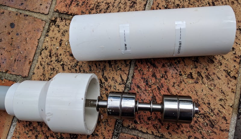
The bottom holds the water level switch and because the switch is just 32mm wide and the conduit I used before is only available in 32mm, I could not use conduit anymore and had to use a larger pipe. My choice fell onto 40mm PVC pressure pipe that protects the whole switch, a 40x25mm reducing coupling, a 25x20mm PVC reducing bush and a 20mm PVC cap end.
I drilled a hole into the cap end and mounted the water level switch into the cap. The reducing bush just fits into the top end of the reducing coupling, and I used super glue to stick the cap with the switch to that reducing bush through the large end of the coupling.
Because the conduit and the pressure pipe are not really made for each other, I had to use some duct tape around the end of the conduit to make it tightly fit into the pressure pipe, and added a bit of super glue to keep everything together.

I drilled a couple of small holes into the back of the large pressure pipe to ensure that water can ingress.
The marks on the outside of the pressure pipe indicate the water level at which the switch turns on. This corresponds to the centre seam of the float.
Display switch states in Home Assistant
Setting up the sensors
The two switches are presented to Home Assistant as binary sensors. The state_topic corresponds to the previous configuration. To better distinguish multiple ESPEasy devices and sensors, I am using the entity_namespace reflecting the device’s name. This is combined with the sensor name to form the sensor’s entity ID.
binary_sensor:
  - platform: mqtt
    entity_namespace: espeasy_01_pool
    state_topic: "espeasy/espeasy-01-pool/waterlevel-low"
    name: "Water Level Low"
    payload_on: "1"
    payload_off: "0"
  - platform: mqtt
    entity_namespace: espeasy_01_pool
    state_topic: "espeasy/espeasy-01-pool/waterlevel-critical"
    name: "Water Level Critical"
    payload_on: "1"
    payload_off: "0"
Avoiding jitter
The water level switches are fairly sensitive to waves. So, if I was just using their on/off state directly to trigger any actions or notifications, a fun hour in the pool could cause the switches to turn on and off all the time and trigger actions more often than I would want. To avoid that I decided to wrap their states into a template sensor each that only turns on/off if the actual switch is on/off for at least 5 minutes.
binary_sensor:
  - platform: template
    sensors:
      pool_water_level_low:
        value_template: "{{ is_state('binary_sensor.espeasy_01_pool_water_level_low', 'on') }}"
        delay_on:
          minutes: 5
        delay_off:
          minutes: 5
        friendly_name: "Water Level Low"
        device_class: safety
      pool_water_level_critical:
        value_template: "{{ is_state('binary_sensor.espeasy_01_pool_water_level_critical', 'on') }}"
        delay_on:
          minutes: 5
        delay_off:
          minutes: 5
        friendly_name: "Water Level Critical"
        device_class: safety
Hiding the raw data sensors
With the above template sensors in place, the original ones are not required to be displayed in the UI, so they can just be hidden. If you are using packages then the below configuration snippet can go straight into the package file together with all sensors and automations.
homeassistant:
  customize:
    binary_sensor.espeasy_01_pool_water_level_low:
      hidden: true
    binary_sensor.espeasy_01_pool_water_level_critical:
      hidden: true
Display water level state in Home Assistant UI and HADashboard
At this point I can distinguish three water level states – normal, low and critical. The following template sensor definition combines these three states into a single sensor.
sensor:
  - platform: template
    sensors:
      pool_water_level:
        value_template: '{% if is_state("binary_sensor.pool_water_level_critical", "on") %}critical{% elif is_state("binary_sensor.pool_water_level_low", "on") %}low{% else %}normal{% endif %}'
        icon_template: '{% if is_state("binary_sensor.pool_water_level_critical", "on") %}mdi:close-circle{% elif is_state("binary_sensor.pool_water_level_low", "on") %}mdi:alert-circle{% else %}mdi:check-circle{% endif %}'
        friendly_name: "Water Level"
The below screenshot shows a point in time when the water level was low but not yet critical.

On my dashboard I do not need to show the details but just the overall water level state.
pool_water_level:
  widget_type: sensor
  title: Pool Water Level
  entity: sensor.pool_water_level
  value_style: "font-size: 150%"
I have not yet found a way to display a textual sensor state with an icon, but ideally it would be nice to show a large coloured icon corresponding to the sensor state.

Reporting
Under normal circumstance I am not expecting to see the water levels changing frequently so I though sending myself a message might be helpful. The following automation sends a notification via Pushover whenever the water level changes. The message just show the textual value and since Pushover supports HTML formatted messages I use text colour to distinguish states.
automation:
  - alias: 'Report Pool Water Level'
    trigger:
      platform: state
      entity_id: sensor.pool_water_level
    action:
      service: notify.pushover
      data_template:
        message: "Pool Water Level changed to: <font color='{%- if is_state('sensor.pool_water_level', 'normal') -%}#0000ff{%- else -%}#ff0000{%- endif -%}'>{{states.sensor.pool_water_level.state}}</font>."
        title: "Pool Water Level"
        data:
          html: 1

Controlling the pool pump
The switch that is triggered by a critically low water level is at about height where the pool pump will not receive a sufficient amount of water to work efficiently.
A future improvement of my automated pool pump will be to check if the water level is not at a critical level, and if it is to either stop the pump or prevent it from starting.
Refilling the pool
Another future improvement could be to automatically refill the pool. At the moment I am not in a position to automate this task but my high-level idea would be to install an irrigation system that could pump water from a tap or rain water tank into the pool.
Ideally this automation should consider the weather forecast, i.e. if rain is predicted or a very hot sunny day, wait a bit. The other challenge when refilling the pool is – how much or how long? So, I would either need to have another pair of water level switches that indicate the preferred water level and the absolute maximum; or, I would need to measure how much water flows into the pool.
Outlook
In my next post I will explain how I monitor the level of liquid chlorine remaining in a drum behind my pool that feeds the chlorinator. Please bear with me – this sensor still needs some more time to be mounted and fine-tuned.
Compatibility
At the time of writing this post, I used:
- Home Assistant 0.57.2 with Python 3.5.1
- ESPEasy v2.0.0-dev12 (dev_4096 build)
- Wemos D1 mini Pro
Leave a Reply to malte Cancel reply