Since my pool is purely heated by the sun, I thought knowing the current water temperature might help in choosing the right outfit – boardshorts or wetsuit – or choose to better stay out of the pool altogether.
I know that you can buy pool water temperature sensors off the shelve, but most are either swimming in the pool and you have to go there to read the temperature value, or they come with a simple wireless display that you can hang into your kitchen, or they are part of an expensive spa&pool controller system. And most of these solutions are not really integrating well into a home automation system. So, building my own device was the obvious things to do here.
Building the device
As I have previously explained, I picked ESP8266 boards and ESPEasy firmware for custom devices. In this case my choice fell onto the WEMOS D1 mini Pro as the basis for this sensor, and probably several more to come. This particular board has one very useful feature for my pool sensor: the built-in antenna can be replaced with an external one. This way, the board itself can sit safely tucked away behind the pool, while the external antenna can be mounted high above the pool to reach my Wifi. Other than that the board is small but provides enough pins to connect several sensors. The easiest way to power the board is via its micro USB connector, and it can provide 3.3V and 5V to sensors.
Connecting the temperature sensor

Luckily there is a waterproof Dallas DS18B20 sensor available on a 1 metre cable that can easily be attached as shown in the following breadboard view.

| DS18B20 Sensor | ESP |
| GND (black wire) | GND |
| DQ (yellow wire) | D7 |
| VCC (red wire) | VCC (3.3V) |
In addition, mount a 4.7kΩ (4k7) resistor between VCC and D7.
I decided to go with a single temperature sensor for now, but you can add more sensors in parallel connected to the same input pin.
Even though the above shows the breadboard view, I actually mounted the components onto a universal matrix prototype PCB – ESP board and sensors through headers and other components like resistors directly soldered onto the PCB.

Configuring ESPEasy
Since this is the first post about the pool sensor, let me briefly show you my general configuration with the focus on how that works with Home Assistant.
In preparation of the following I assume that you have followed the general installation steps – uploading the firmware onto the device, connecting to its built-in access point, configuring the device to connect to your Wifi, and then being able to access the ESPEasy web interface.
MQTT configuration
Since I already had Mosquitto MQTT broker running on my Home Assistant host, I decided to go with MQTT here, too. The “OpenHAB MQTT” protocol works just fine with Home Assistant, but I added espeasy/ as a static prefix, and removed the %tskname%/ part from the default subscribe/publish configuration. So far I haven’t seen how adding the task name in there would add any value.

When sending values to the broker, %sysname% is replaced with the unit name, and %valname% is replaced with each device’s value name.
Configuring water temperature sensor
The temperature sensor is added as a new device in the ESPEasy web interface. Pick “P004 – Environment – DS18b20” from the Device dropdown, then select the input pin (D7 in my example), and the device address (should only be one if only one sensor is connected). I gave my sensor the name “watertemperature” and get the value sent via MQTT every 10 minutes.

Once the sensor is reporting its values to the MQTT broker as expected I would also recommend to publish retained messages. That way Home Assistant always has a value to display after restarting. Go to “Tools” → “Advanced”, check the “MQTT Retain Msg” checkbox and click the “Submit” button.
Mounting the temperature sensor in the pool
Of course I did not want to just hang the temperature sensor into the water, so I went to my favourite hardware store and got some bits and pieces to build myself a nice enclosure, well, or at least a functional one.

The actual temperature sensor is at the very bottom of the enclosure so that it is alway under water even with varying water levels. The enclosure is held by a conduit mounting clip that is fixed with a screw and ramplug in the pool’s brick coping.

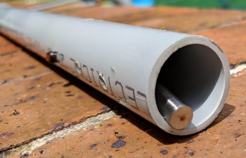
The whole enclosure consists of a long piece of 25mm conduit, an elbow bend, and a 25mm conduit plug. I drilled a hole into that plug to mount a cable gland.

To ensure that the temperature sensor remains at the bottom, I threaded its cable through a hole drilled into a 20mm conduit plug which fits into the 25mm conduit where it is fixed with a small screw about 10cm away from the bottom. I drilled a few holes into the conduit between that plug and the sensor to ensure that water can ingress.
Mounting the board and electronics
I put some effort into making this whole solution reasonably weatherproof:
- The ESP board and the electronics are tucked away in an IP65 rated ABS enclosure.
- I chose waterproof SP1310 connectors – in case of the water temperature sensor the 3-pin version – with the socket mounted in the enclosure.
- Cables between the sensor and the enclosure are in a braided PET sleeving that hopefully protects against UV rays.
- The USB cable used for power goes through a cable gland into the enclosure, directly connected to the ESP board.

The enclosure is mounted on a brick wall under/behind my pool, but it’s not fully protected against rain and sun. The connectors to the sensors are at the bottom, the USB power cables exits on the right and ends up in the power board enclosure I covered in a previous post. The Wifi antenna connector is on the left.

Display water temperature in Home Assistant
Now that the devices are mounted, and ESPEasy is connected to Wifi and MQTT broker, there is a little bit of configuration required in Home Assistant to display the water temperature.
Setting up the sensor
The configuration itself is fairly simple. The state_topic corresponds to the previous configuration. To better distinguish multiple ESPEasy devices and sensors, I am using the entity_namespace reflecting the device’s name. This is combined with the sensor name to form the sensor’s entity ID.
sensor:
  - platform: mqtt
    entity_namespace: espeasy_01_pool
    state_topic: 'espeasy/espeasy-01-pool/watertemperature'
    force_update: true
    name: 'Water Temperature'
    unit_of_measurement: '°C'
    value_template: '{{ value | round(1) }}'
Since the water temperature is only changing slowly, I set force_update to true.
Display water temperature in Home Assistant UI and on HADashboard


Outlook
As you can guess from the picture of the sensor’s enclosure I added a few more things. In the next post I will explain how I monitor the water level.
Leave a Reply to Michael lindborg Cancel reply